Program ATtiny85 with Arduino Nano
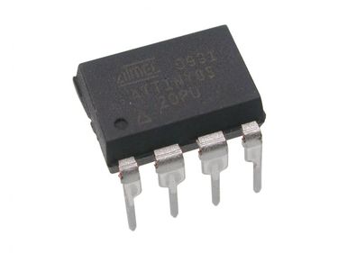
07 Aug 2017Recently I was working on a project with Arduino Nano. To fit the entire project into a 3D printed closure with limited space, I was searching for ways to shrink down the physical footprint of the Arduino Nano board. That’s when I came across this video, in which it mentioned the ATtiny85 chip. It is a variant of a family of Arduino compatible 8-bit controllers with only 8 pins. The small form factor fits the bill perfectly, plus I can use the same code for Nano as long as it can fit into chip’s 8KB memory.
After some digging, it turns out the video was based on two blog posts from MIT Media Lab’s High-Low Tech group: Programming an ATtiny w/ Arduino 1.6 (or 1.0) and Arduino board as ATtiny programmer. The idea behind the posts is really simple: use Arduino Uno as an in-system programmer (ISP) to upload Arduino code to ATtiny85. Albeit I only have an Arduino Nano, the instructions are quite straightforward to follow. However, judging from the software versions, the posts were there for a while, and I did run into some troubles. So I decide to summarize the procedures I took to make it work.
# Load Arduino Nano with ISP Program
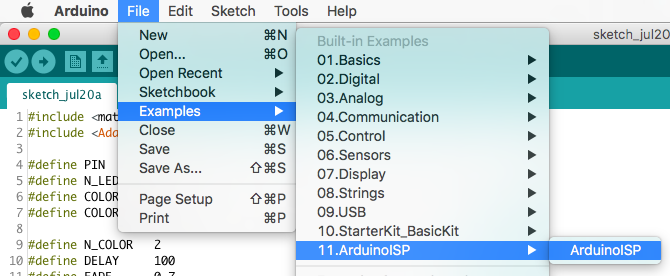
Step 1: open Arduino IDE (for this, I am using the newest version of 1.8.3), and open the ArduinoISP sketch in Examples.
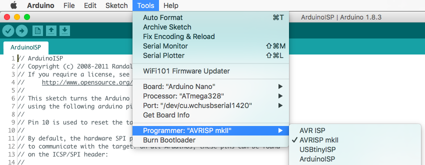
Step 2: make sure the programmer is set to AVRISP mkII, because we need to upload the sketch to Nano first.
Step 3: upload it and… Done! (Well, for now…)
# Wire Up
Follow this wiring diagram to connect ATtiny85 with Arduino Nano.
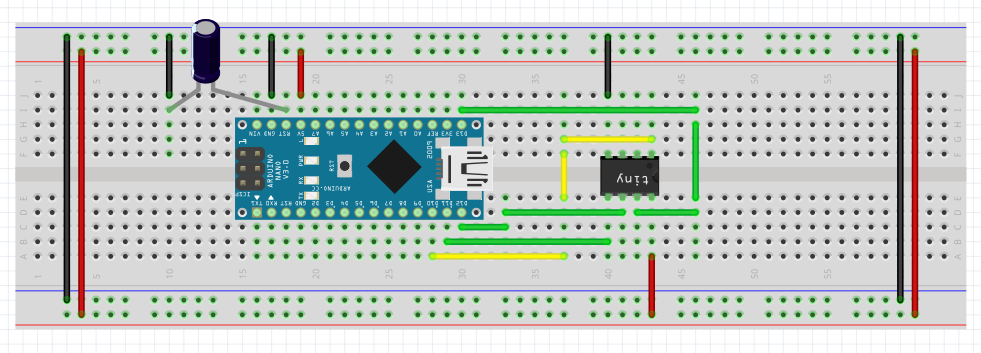
Here are some tips:
- You need a 10uF capacitor between Nano’s reset (RST) and ground (GND) to prevent Nano from resetting during upload
- Nano pin 13 -> ATtiny85 pin 2
- Nano pin 12 -> ATtiny85 pin 1
- Nano pin 11 -> ATtiny85 pin 0
- Nano pin 10 -> ATtiny85 Reset
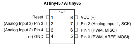
Nano’s pins are clearly labeled on the board. In case you are wondering about the pin on ATtiny85, here is the pin layout diagram.
# Install ATtiny Boards
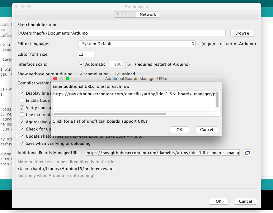
Step 1: open Preferences in Arduino IDE, and add https://raw.githubusercontent.com/damellis/attiny/ide-1.6.x-boards-manager/package_damellis_attiny_index.json to Additional Boards Manager URLs.
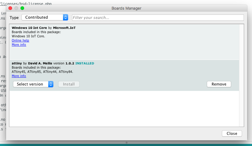
Step 2: open Board Manager and install attiny boards.

# Upload Code
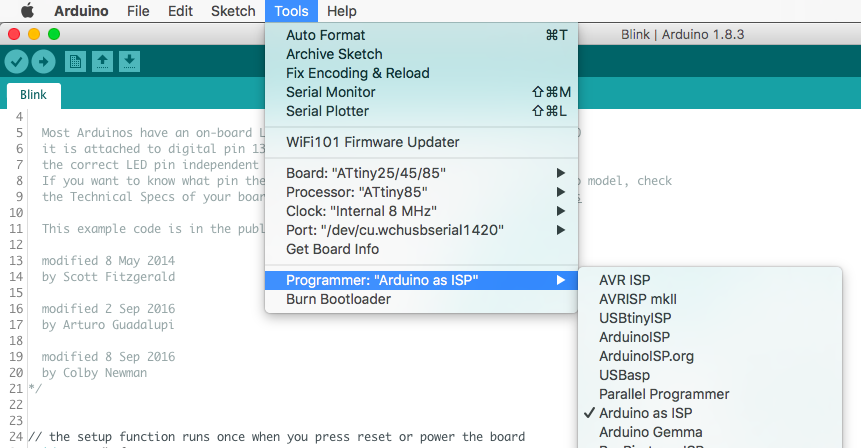
Right before uploading the code, we need to burn the bootloader to the brand new ATtiny85 chip with the following settings. Once bootloader is ready, upload the code, and make sure to select programmer as Arduino as ISP.
